Expérimentation zigBee
Comment réaliser des appareils zigBee à partir de microcontrôleurs Expressif
Les modules actuellement (8/1/25) capable d’intégrer un réseau zigbee sont:
- ESP32-H2 32-bit RISC-V MCU & Bluetooth 5 (LE) & IEEE 802.15.4 (zigBee)
- ESP32-C6 32-bit RISC-V MCU & 2.4 GHz Wi-Fi 6 & Bluetooth 5 (LE) & IEEE 802.15.4 (zigBee)


Différence entre le C6 et le H2.
| fonction | H2 | C6 |
|---|---|---|
| Wifi | Non | 802.11b/g/n |
| Flash | 4 MB | 8 MB |
| I/face | 2x USB C | 2x USB C |
| UI | Buttons | Buttons |
| LED | Power/RGB | Power/RGB |
| BT LE | 5.3 | 5.3 |
| zigBee | 2015 compliant | 2015 compliant |
La version C6 est nettement plus performante, son Wifi permet des viteses de 150 Mbps et possède 4 innterfaces virtuel (l’ESP peut donc connecter un AP et créer un AP sur l’ESP), la vitesse d’horloge est de 160 MHz contre 96 pour le H2.
Au niveau du prix, les deux ne dépassent pas les 5€
Premier essai réalisation d’un Scanneur de réseau zigBee:
Module utilisé ESP-32 Wroom C6 Le but: scanner les fréquences zigbee sur 2.4 GHz et détecter les réseaux présents.
Pour programmer ces modules via l’Arduino IDE il faut absolument installer le core esp32 d’Expressif dans le dernier IDE (préférence/settings -> additional URL board manager insérer l’URL suivante https://espressif.github.io/arduino-esp32/package_esp32_index.json )
Ensuite le code réalisé sur base de l’example Network Scan, attention dans tools il faut sélectionner partition scheme zigbee 4MB with spiffs pour bien spécifier le mode de partition du firmware. Le mode zigBee (Coordinator/router). A noter que le circuit d’interface ayant changé un nouveau driver sera sans doute nécessaire pour charger le firmware compilé sur le contrôleur (pour ma part j’ai utilisé un driver CH343 sur mon MacBook, Linux lui doit avoir le driver par defaut.
J’aurais bien voulu complèter les fonctionalités par un scanneur de WiFi, malheureusement, les librairies ne permettent pas encore d’activer le WiFi en même temps que le zigBee.
code scanner zigbee
// Copyright 2024 Espressif Systems (Shanghai) PTE LTD
//
// Licensed under the Apache License, Version 2.0 (the "License");
// you may not use this file except in compliance with the License.
// You may obtain a copy of the License at

//     http://www.apache.org/licenses/LICENSE-2.0
//
// Unless required by applicable law or agreed to in writing, software
// distributed under the License is distributed on an "AS IS" BASIS,
// WITHOUT WARRANTIES OR CONDITIONS OF ANY KIND, either express or implied.
// See the License for the specific language governing permissions and
// limitations under the License.

/**
* @brief This example demonstrates Zigbee Network Scanning.
*
* The example demonstrates how to use ESP Zigbee stack to scan for Zigbee networks.
*
* Any Zigbee mode can be selected in Tools->Zigbee mode
* with proper Zigbee partition scheme in Tools->Partition Scheme.
*
* Please check the README.md for instructions and more detailed description.
*
* Created by Jan Procházka (https://github.com/P-R-O-C-H-Y/)
*/


#include <Adafruit_NeoPixel.h>  // RGB LED colour

#define LED_PIN 8  // The ESP32-C6 pin connected to the built-in RGB LED
#define NUM_LEDS 1

Adafruit_NeoPixel rgbLed(NUM_LEDS, LED_PIN, NEO_GRB + NEO_KHZ800);

struct RGB {
    uint8_t r, g, b;
};

constexpr RGB COLOR_OFF = {0, 0, 0};
constexpr RGB COLOR_RED = {255, 0, 0};
constexpr RGB COLOR_GREEN = {0,255,0};
constexpr RGB COLOR_BLUE = {0,0,255};


#if !defined(ZIGBEE_MODE_ED) && !defined(ZIGBEE_MODE_ZCZR)
#error "Zigbee device mode is not selected in Tools->Zigbee mode"
#endif

#include "Zigbee.h"


#ifdef ZIGBEE_MODE_ZCZR
zigbee_role_t role = ZIGBEE_ROUTER;  // or can be ZIGBEE_COORDINATOR, but it won't scan itself
#else
zigbee_role_t role = ZIGBEE_END_DEVICE;
#endif

void setColor(const RGB& color) {
    rgbLed.setPixelColor(0, rgbLed.Color(color.r, color.g, color.b));
    rgbLed.show();
}


void printScannedNetworks(uint16_t networksFound) {
if (networksFound == 0) {
    setColor(COLOR_RED);
    Serial.println("No networks found");
} else {
    setColor(COLOR_GREEN);
    zigbee_scan_result_t *scan_result = Zigbee.getScanResult();
    Serial.println("\nScan done");
    Serial.print(networksFound);
    Serial.println(" networks found:");
    Serial.println("Nr | PAN ID | CH | Permit Joining | Router Capacity | End Device Capacity | Extended PAN ID");
    for (int i = 0; i < networksFound; ++i) {
    // Print all available info for each network found
    Serial.printf("%2d", i + 1);
    Serial.print(" | ");
    Serial.printf("0x%04hx", scan_result[i].short_pan_id);
    Serial.print(" | ");
    Serial.printf("%2d", scan_result[i].logic_channel);
    Serial.print(" | ");
    Serial.printf("%-14.14s", scan_result[i].permit_joining ? "Yes" : "No");
    Serial.print(" | ");
    Serial.printf("%-15.15s", scan_result[i].router_capacity ? "Yes" : "No");
    Serial.print(" | ");
    Serial.printf("%-19.19s", scan_result[i].end_device_capacity ? "Yes" : "No");
    Serial.print(" | ");
    Serial.printf(
        "%02x:%02x:%02x:%02x:%02x:%02x:%02x:%02x", scan_result[i].extended_pan_id[7], scan_result[i].extended_pan_id[6], scan_result[i].extended_pan_id[5],
        scan_result[i].extended_pan_id[4], scan_result[i].extended_pan_id[3], scan_result[i].extended_pan_id[2], scan_result[i].extended_pan_id[1],
        scan_result[i].extended_pan_id[0]
    );
    Serial.println();
    delay(10);
    }
    Serial.println("");
    // Delete the scan result to free memory for code below.
    Zigbee.scanDelete();
}
}

void setup() {
Serial.begin(115200);
rgbLed.begin();
rgbLed.show();

// Initialize Zigbee stack without any EPs just for scanning
if (!Zigbee.begin(role)) {
    Serial.println("Zigbee failed to start!");
    Serial.println("Rebooting...");
    ESP.restart();
}

    // Set WiFi to station mode and disconnect from an AP if it was previously connected.


Serial.println("Setup done, starting Zigbee network scan...");
// Start Zigbee Network Scan with default parameters (all channels, scan time 5)

Zigbee.scanNetworks();
}

void loop() {
// check Zigbee Network Scan process
int16_t ZigbeeScanStatus = Zigbee.scanComplete();
if (ZigbeeScanStatus < 0) {  // it is busy scanning or got an error
    if (ZigbeeScanStatus == ZB_SCAN_FAILED) {
    Serial.println("Zigbee scan has failed. Starting again.");
    Zigbee.scanNetworks();
    }
    // other option is status ZB_SCAN_RUNNING - just wait.
} else {  // Found Zero or more Wireless Networks
    printScannedNetworks(ZigbeeScanStatus);
    setColor(COLOR_BLUE);
    Zigbee.scanNetworks();  // start over...
}

/* Loop can do something else...


delay(500);
Serial.print(".");
}
test du scanner
La sortie série est utilisée pour communiquer avec le module et indique la détection de deux réseaux zigBee.
- Le réseau 0x1a62 est un réseau Phoscon/CONBEE II
- Le réseau 0xb596 est une réseau sur zigbee2mqtt (dongle SONOFF)
!(serial output)[/images/zigbee/temp_sensor_end_device/output.png]
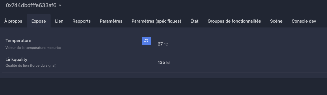
Deuxième essai, end device avec lecture de température (CPU)
Utilisation d’un ESP32-H2.
Utilisation du code de l’example Zigbee/example/Temperature_sensor_end_device, compilation et upload en suivant les directive énnoncées ci-dessus.
Code sonde de témpérature
// Copyright 2024 Espressif Systems (Shanghai) PTE LTD
//
// Licensed under the Apache License, Version 2.0 (the "License");
// you may not use this file except in compliance with the License.
// You may obtain a copy of the License at
//
//     http://www.apache.org/licenses/LICENSE-2.0
//
// Unless required by applicable law or agreed to in writing, software
// distributed under the License is distributed on an "AS IS" BASIS,
// WITHOUT WARRANTIES OR CONDITIONS OF ANY KIND, either express or implied.
// See the License for the specific language governing permissions and
// limitations under the License.

/**
* @brief This example demonstrates Zigbee temperature sensor.
*
* The example demonstrates how to use Zigbee library to create a end device temperature sensor.
* The temperature sensor is a Zigbee end device, which is controlled by a Zigbee coordinator.
*
* Proper Zigbee mode must be selected in Tools->Zigbee mode
* and also the correct partition scheme must be selected in Tools->Partition Scheme.
*
* Please check the README.md for instructions and more detailed description.
*
* Created by Jan Procházka (https://github.com/P-R-O-C-H-Y/)
*/

#ifndef ZIGBEE_MODE_ED
#error "Zigbee end device mode is not selected in Tools->Zigbee mode"
#endif

#include "Zigbee.h"

/* Zigbee temperature sensor configuration */
#define TEMP_SENSOR_ENDPOINT_NUMBER 10
uint8_t button = BOOT_PIN;

ZigbeeTempSensor zbTempSensor = ZigbeeTempSensor(TEMP_SENSOR_ENDPOINT_NUMBER);

/************************ Temp sensor *****************************/
static void temp_sensor_value_update(void *arg) {
for (;;) {
    // Read temperature sensor value
    float tsens_value = temperatureRead();
    Serial.printf("Updated temperature sensor value to %.2f°C\r\n", tsens_value);
    // Update temperature value in Temperature sensor EP
    zbTempSensor.setTemperature(tsens_value);
    delay(1000);
}
}

/********************* Arduino functions **************************/
void setup() {
Serial.begin(115200);

// Init button switch
pinMode(button, INPUT_PULLUP);

// Optional: set Zigbee device name and model
zbTempSensor.setManufacturerAndModel("Espressif", "ZigbeeTempSensor");

// Set minimum and maximum temperature measurement value (10-50°C is default range for chip temperature measurement)
zbTempSensor.setMinMaxValue(10, 50);

// Optional: Set tolerance for temperature measurement in °C (lowest possible value is 0.01°C)
zbTempSensor.setTolerance(1);

// Add endpoint to Zigbee Core
Zigbee.addEndpoint(&zbTempSensor);

Serial.println("Starting Zigbee...");
// When all EPs are registered, start Zigbee in End Device mode
if (!Zigbee.begin()) {
    Serial.println("Zigbee failed to start!");
    Serial.println("Rebooting...");
    ESP.restart();
} else {
    Serial.println("Zigbee started successfully!");
}
Serial.println("Connecting to network");
while (!Zigbee.connected()) {
    Serial.print(".");
    delay(100);
}
Serial.println();

// Start Temperature sensor reading task
xTaskCreate(temp_sensor_value_update, "temp_sensor_update", 2048, NULL, 10, NULL);

// Set reporting interval for temperature measurement in seconds, must be called after Zigbee.begin()
// min_interval and max_interval in seconds, delta (temp change in 0,1 °C)
// if min = 1 and max = 0, reporting is sent only when temperature changes by delta
// if min = 0 and max = 10, reporting is sent every 10 seconds or temperature changes by delta
// if min = 0, max = 10 and delta = 0, reporting is sent every 10 seconds regardless of temperature change
zbTempSensor.setReporting(1, 0, 1);
}

void loop() {
// Checking button for factory reset
if (digitalRead(button) == LOW) {  // Push button pressed
    // Key debounce handling
    delay(100);
    int startTime = millis();
    while (digitalRead(button) == LOW) {
    delay(50);
    if ((millis() - startTime) > 3000) {
        // If key pressed for more than 3secs, factory reset Zigbee and reboot
        Serial.println("Resetting Zigbee to factory and rebooting in 1s.");
        delay(1000);
        Zigbee.factoryReset();
    }
    }
    zbTempSensor.reportTemperature();
}
delay(100);
}
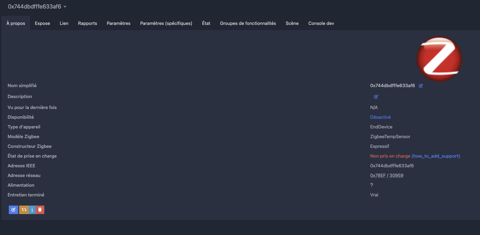
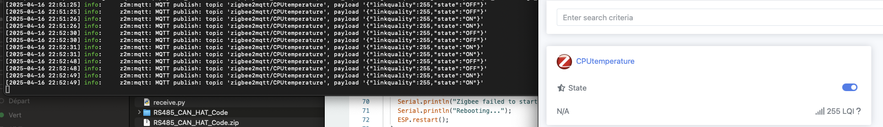
L’appareil se met directment en mode inclusion dans le réseau, ensuite, activation de l’appairage sur zigbeemqtt et l’appareil intégré au réseau.
Comme l’info manufacturer/device n’est pas dans z2m, il n’est pas complètement reconnu.

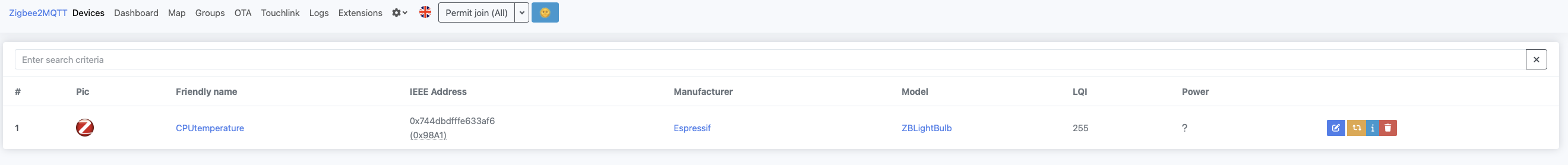
End device switch (exemple expressif)
Voiçi ce que l’exemple proposé par expressif donne (H2), commande de la LED du H2 via Z2M
La définition externe est établie par z2m dans le device console, elle est ensuite écrite dans le directory data/external_converters/ de l’installation
Par exemple myzigbeelight.mjs
import * as m from 'zigbee-herdsman-converters/lib/modernExtend';

export default {
    zigbeeModel: ['ZBLightBulb'],
    model: 'ZBLightBulb',
    vendor: 'Espressif',
    description: 'Automatically generated definition',
    extend: [m.onOff({"powerOnBehavior":false})],
    meta: {},
};